What are "Non-manifold" shapes?
You can generate any shape which comes to your mind using CAD design program as far as you have a rich imagination! But those shapes will give you trouble when trying to manufacture or prototype if you do not properly analyze those geometries. One possible and most common reason is the shapes will have non-manifold shapes. In this article, I briefly describe what are non-manifold shapes and how to identify them.
What is non-manifold geometry?
If you search “What is the meaning of non-manifold geometry?” you will end up with different definitions. Simply, non-manifold geometries are defined as shapes which cannot exist in the real world.
Another definition I found is “A non-manifold geometry is a 3D shape that cannot be unfolded into a 2D surface with all its normals pointing the same direction”. A “2D surface” means a continuous flat surface. The “normal” means the surface normal of the given shape. This can be defined by the user when generating the geometry or the software assigns that automatically. That is based on the design software.
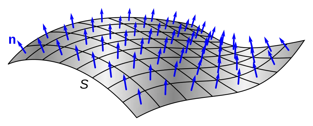 |
| Surface normals (Image courtesy: Wikipedia) |
 |
3D box unfolded into 2D surface |
In 3D geometry generation tools, non-manifold geometry is not considered an issue. But when you try to create a prototype using that geometry using 3D printing, the result will be bad. You need to carefully analyze your geometry before going to that stage.
Types of non-manifold geometries
There are different ways to identify non-manifold geometries.
⚈ Multiply connected geometries
⚈ Surfaces are connected to a single vertex
⚈ Open shapes
⚈ Shapes with internal faces
⚈ Adjacent faces with opposite normals
⚈ Disconnected vertices and edges
Multiply connected geometries
If an edge is shared with more than two faces, that is non-manifold geometry. In most cases, this scenario is mentioned as “T-Shape”.
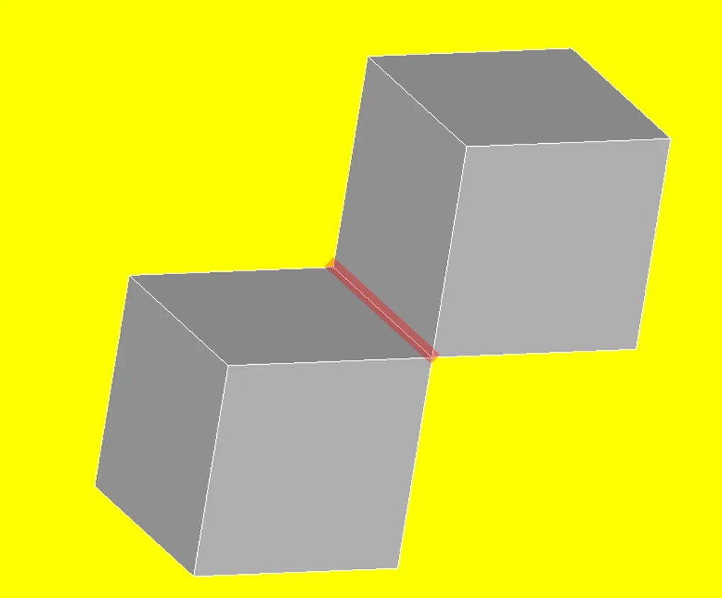 |
Multi connected geometris |
 |
T-Shape |
You can eliminate those geometries by removing the unwanted face from the geometry or, adjusting the shape by giving volume to that.
Surfaces are connected to a single vertex
Two solid bodies will be connected using only one vertex. This is called “bow-type”. Here multiple shapes shared a single vertex but no edge.
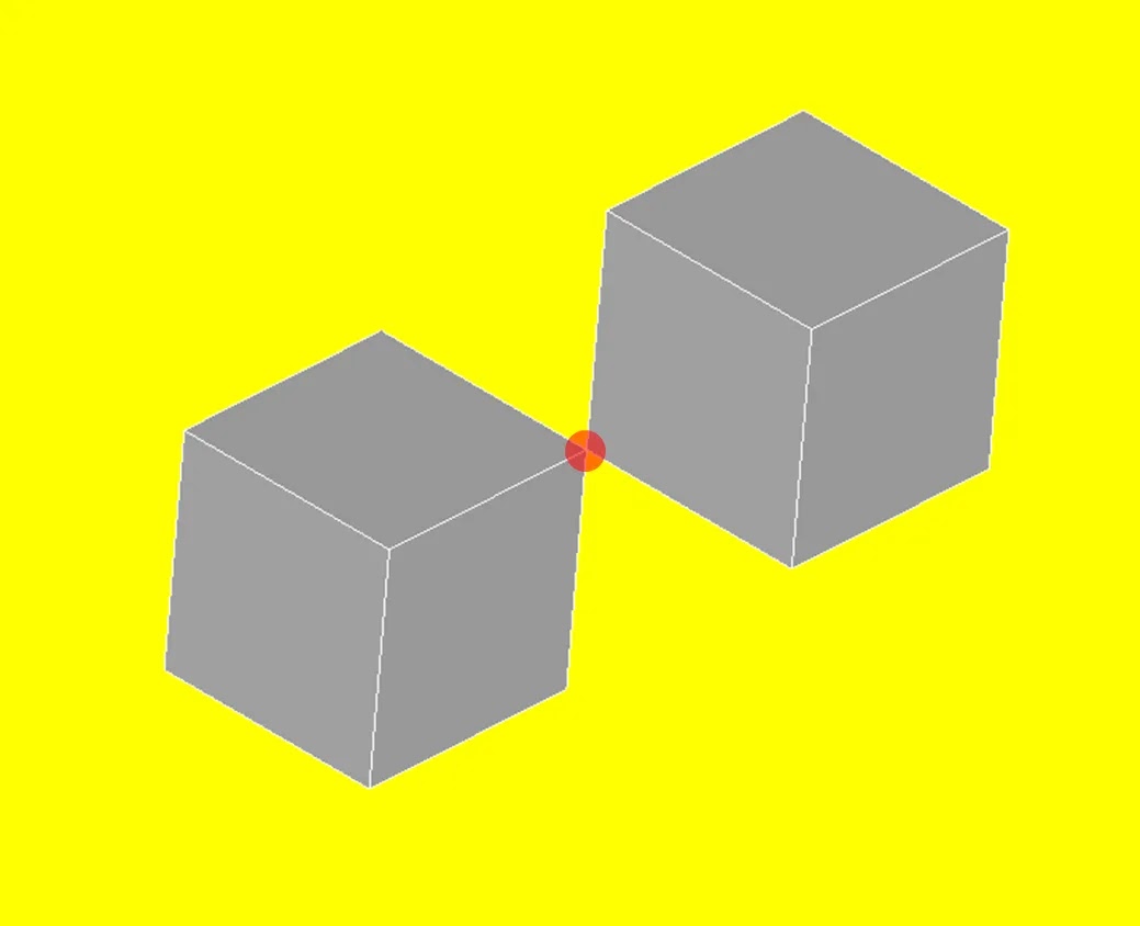 |
Object connected to a single vertex Surface connected to a single vertex |
This can be fixed by separating each geometry or removing one geometry completely.
Open shapes
Shapes can have voids without support. Here the geometry contains zero-volume shapes.
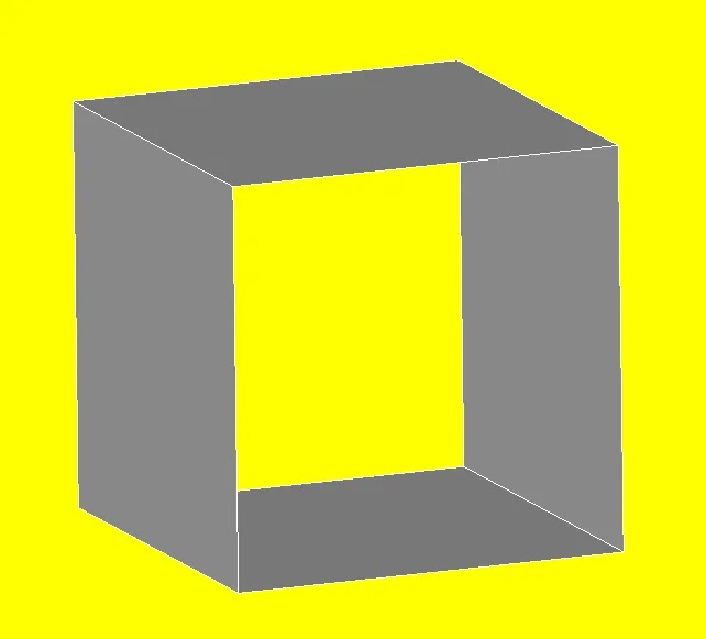 |
Open shape |
These shapes can be fixed by giving thickness to the shell or filling the void completely.
 |
Fill the shape or add thickness |
Shapes with internal faces
Sometimes, internal faces will appear in a given shape which cannot really exists. Actually, these internal faces are not needed to generate the geometry.
 |
Internal face |
This issue can be fixed by deleting the internal face.
Adjacent faces with opposite normals
In mesh generation, sometimes the adjacent faces will contain surface normals in opposite directions.
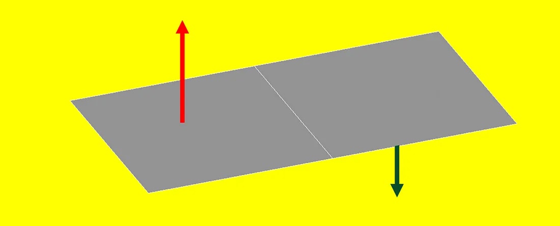 |
Faces with reversed normal |
To fix that, surface normals need to be reversed in a single direction.
Disconnected vertices and edges
Free edges and free vertices will be found in a given geometry. Sometimes, edges and vertices are generated but not connected to the actual geometry.
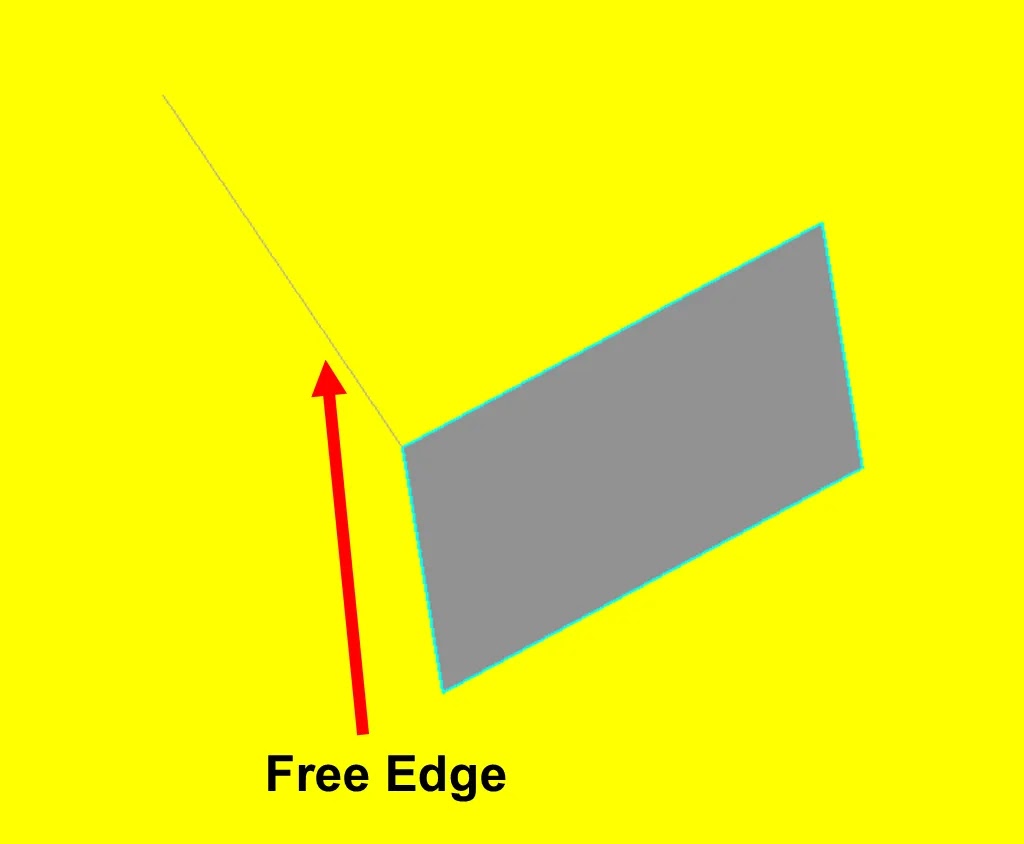 |
Disconnected edge from the geometry (Free edges) |
Analyze your geometry
Analyze your geometry after completion to avoid this kind of defect. This will help you to create sound geometry without any issues in the simulation, manufacturing or prototyping stage.


